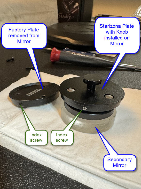
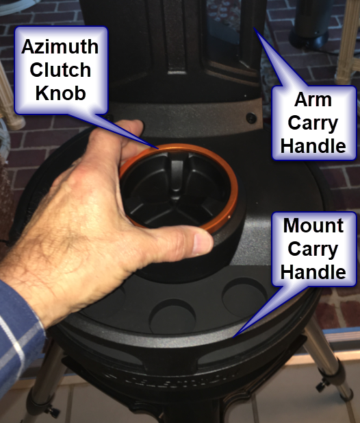
I recently received my Starizona Hyperstar 6v4 for my Celestron 6. My idea is to use my C6 on an Evolution mount for portable outreach at f/2 using my DS10c. I first had to install the Starizona secondary mirror plate with knob onto my C6 secondary mirror to enable it to be easily removed when using the Hyperstar 6. If your Celestron 6” secondary mirror does not have a plate with a knob, click on the link at the end of this post for further instructions.
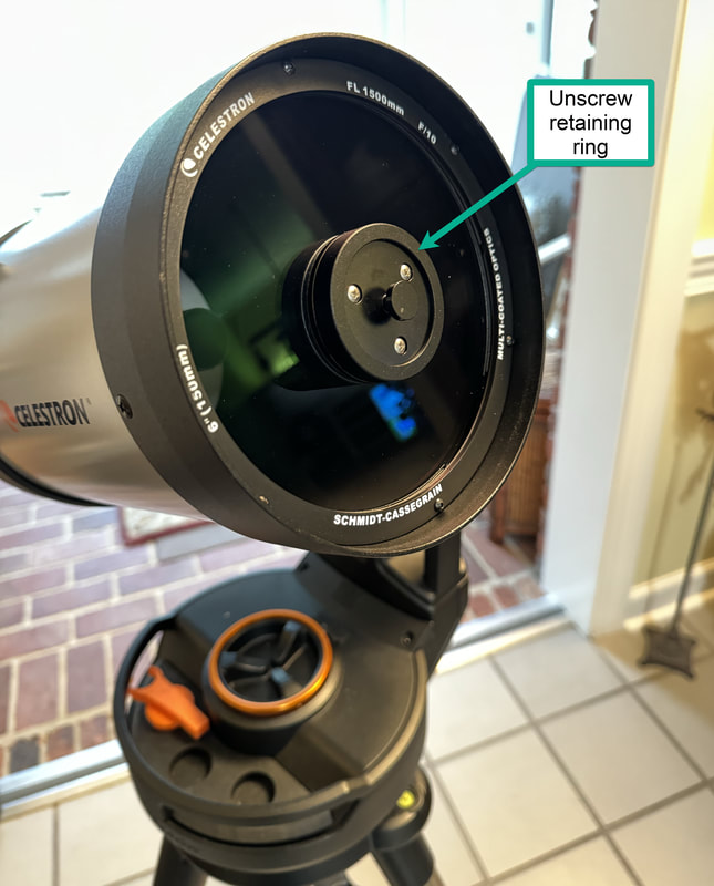
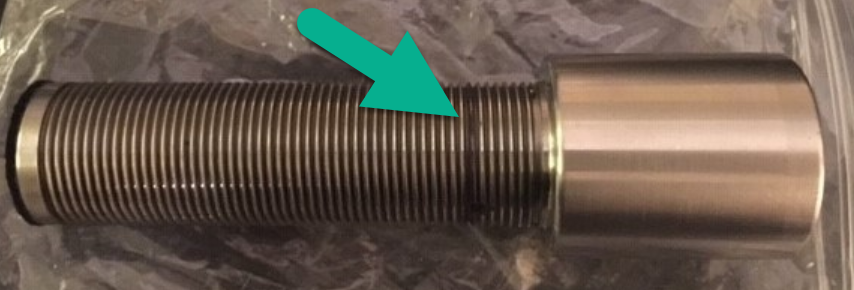
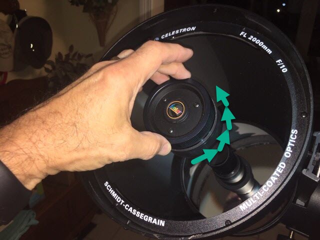
To set up the Hyperstar, position your telescope tilted slightly upward. Then carefully unscrew the secondary mirror retaining ring.
To set up the Hyperstar, position your telescope tilted slightly upward. Then carefully unscrew the secondary mirror retaining ring.
 | 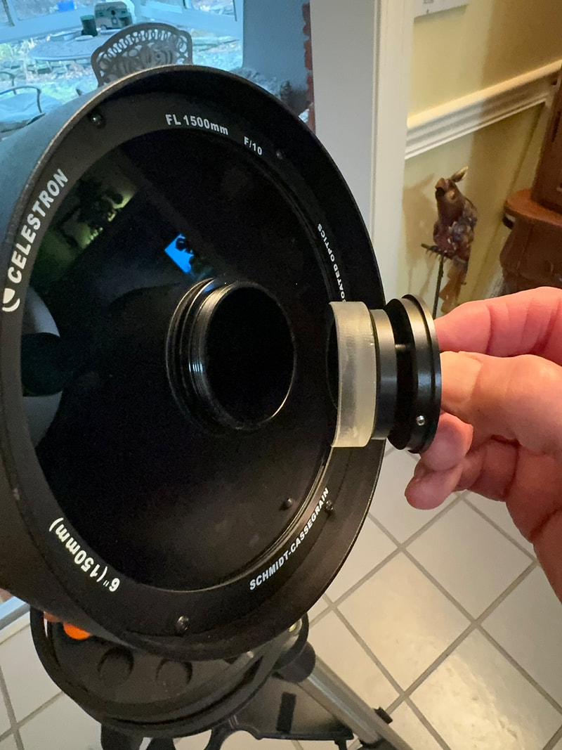 |
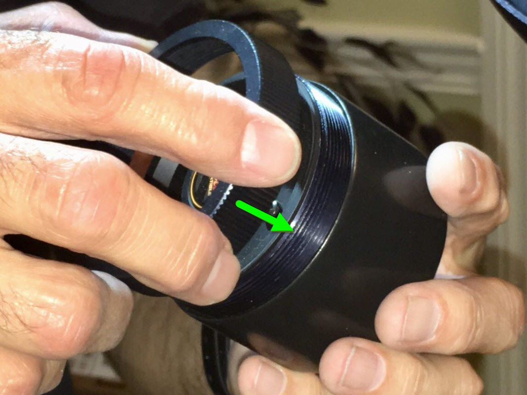
Unscrew the can from the end of the Hyperstar and place it nearby. Grasp the knob to pull the secondary out and then place it in the can you removed from the Hyperstar. Then screw the retaining ring onto the can so the secondary mirror can be safely stored while the Hyperstar is in use.
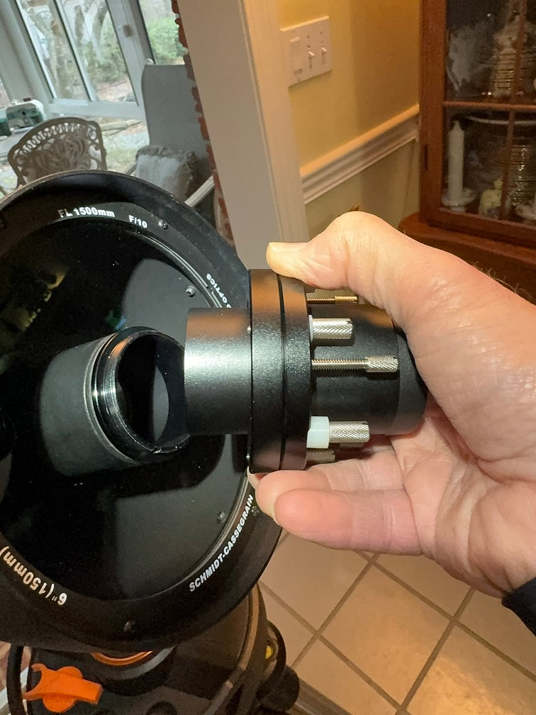
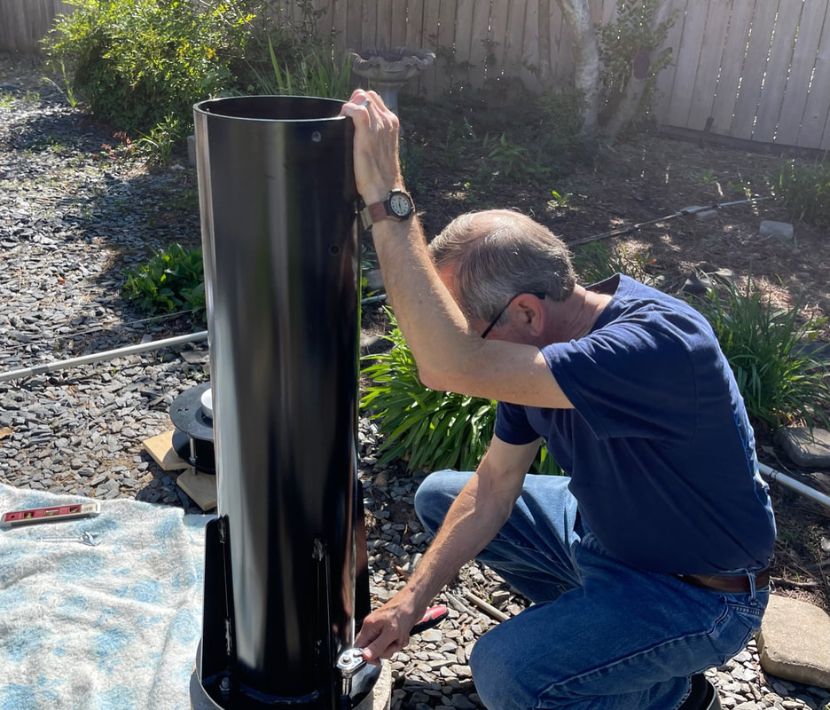
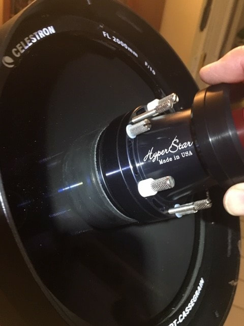
Now carefully insert the Hyperstar where the secondary mirror was removed and screw it in place. Do NOT overtighten - just screw it on until it is slightly snug.
Now carefully insert the Hyperstar where the secondary mirror was removed and screw it in place. Do NOT overtighten - just screw it on until it is slightly snug.
 | 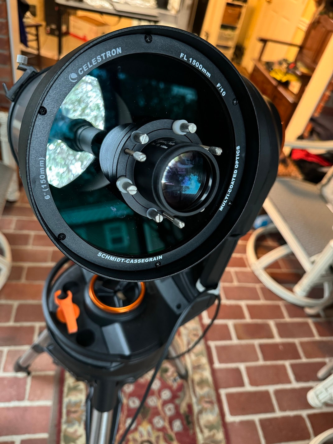 |
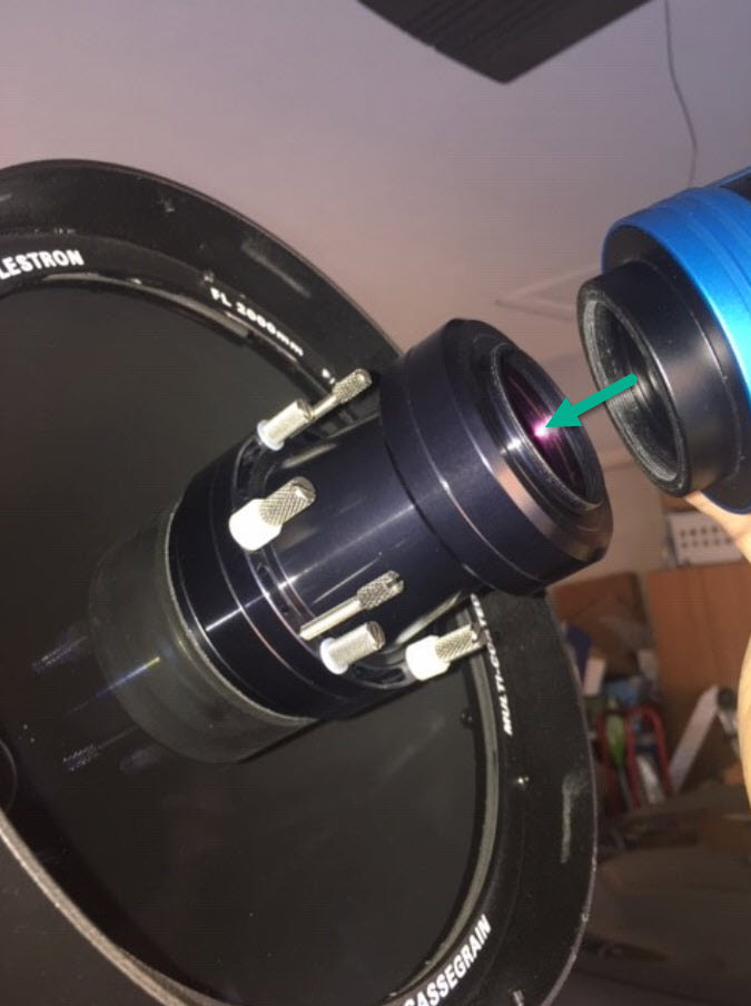
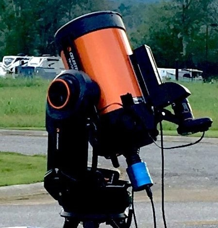
Now screw the camera onto the end of the Hyperstar. Again, screw on until snug, but do not over tighten.

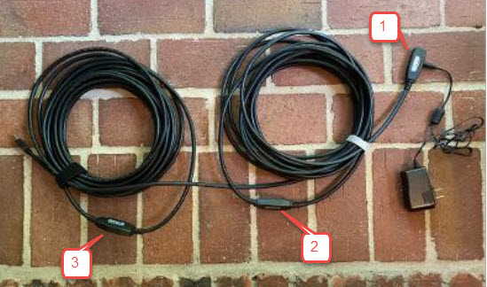
Now attach the USB cable, and if using TEC cooling, attach the power cable.
First Light with Hyperstar C6
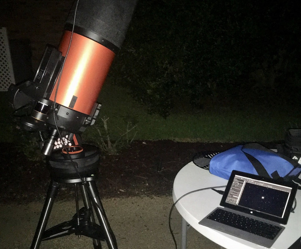
I had my initial HyperStar C6 + DS10c viewing session using the Evolution mount on Monday 2/5/2024. It was a clear night in my backyard and about 45 degrees, but with humidity here in the South of 85%.
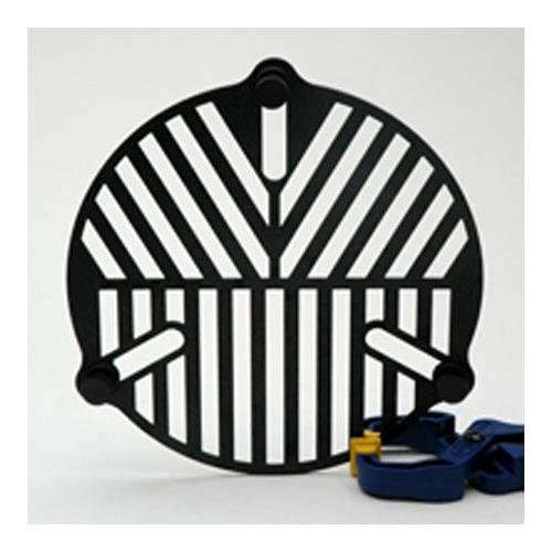
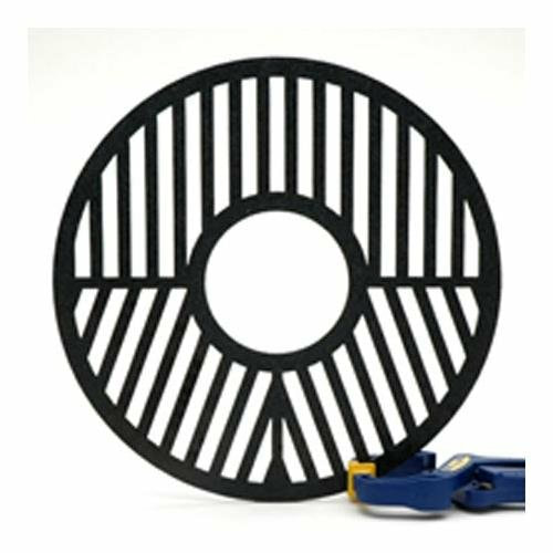
After setting up the C6 on the Evolution mount and adding the Hyperstar 6v4 and DS10c, I performed a StarSense AutoAlign and then slewed to a bright star. Using a Bahtinov focus mask, I focused as best I could, knowing I would have to collimate the Hyperstar since this was its first time use. Having used a Hyperstar on my C8 I was familiar with the process of using the Hyperstar adjusting screws. After a period of time I had a good enough collimation to begin.
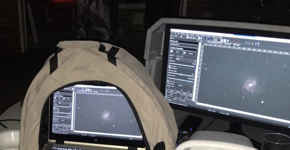
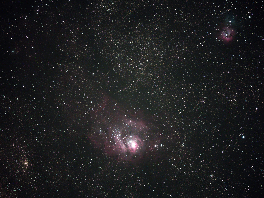
Even though it was clear, I did have to contend with humidity and my Bortle 6 surrounding Skyglow. Due to the conditions, I first checked out star clusters to get a feel of the field of view and exposure time. The DS10c was set at bin 1 for this session. Since this was my first time with this setup, I just have a few examples. With the Hyperstar on the C6, note that star cluster exposure time is under 1 second at bin 1.
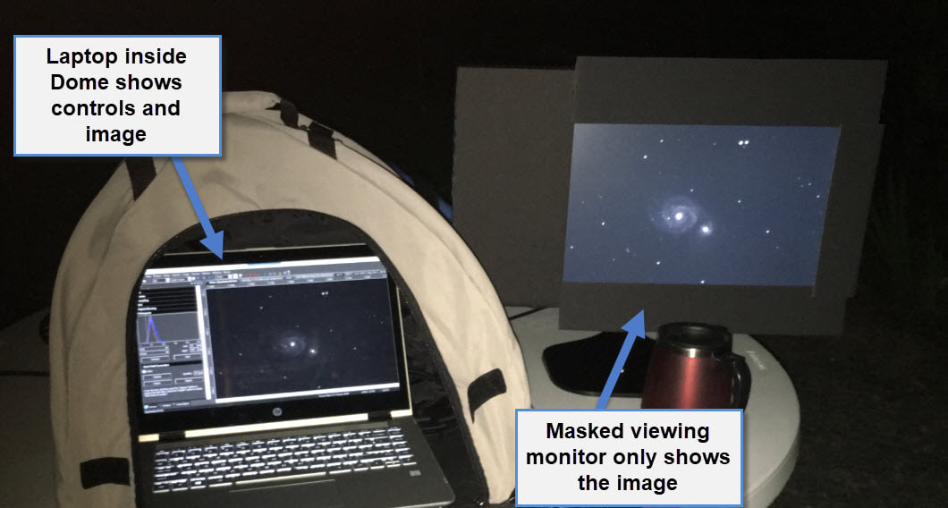
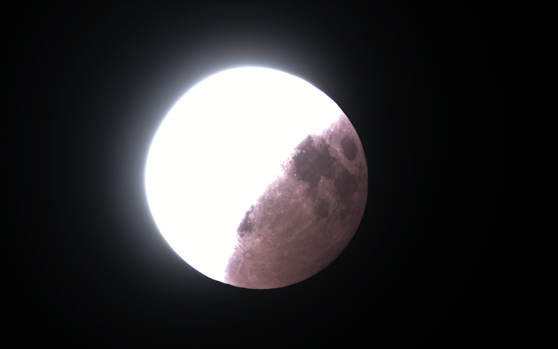
Here are my “first light” image captures using the Hyperstar C6 with a DS10c Video Astronomy camera.
First Light with Hyperstar C6
I had my initial HyperStar C6 + DS10c viewing session using the Evolution mount on Monday 2/5/2024. It was a clear night in my backyard and about 45 degrees, but with humidity here in the South of 85%.
After setting up the C6 on the Evolution mount and adding the Hyperstar 6v4 and DS10c, I performed a StarSense AutoAlign and then slewed to a bright star. Using a Bahtinov focus mask, I focused as best I could, knowing I would have to collimate the Hyperstar since this was its first time use. Having used a Hyperstar on my C8 I was familiar with the process of using the Hyperstar adjusting screws. After a period of time I had a good enough collimation to begin.
Even though it was clear, I did have to contend with humidity and my Bortle 6 surrounding Skyglow. Due to the conditions, I first checked out star clusters to get a feel of the field of view and exposure time. The DS10c was set at bin 1 for this session. Since this was my first time with this setup, I just have a few examples. With the Hyperstar on the C6, note that star cluster exposure time is under 1 second at bin 1.
Here are my “first light” image captures using the Hyperstar C6 with a DS10c Video Astronomy camera.
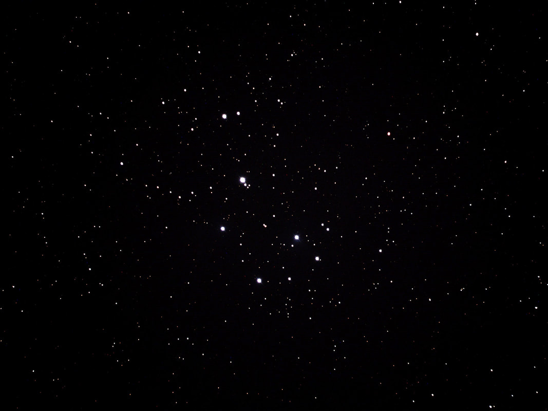
m45 Pleiades
Settings: 0.5 second exposure, 160 gain, 50-255 histogram, 15 stacked images
Settings: 0.5 second exposure, 160 gain, 50-255 histogram, 15 stacked images
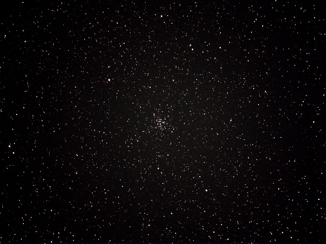
m36 Pinwheel cluster
Settings: 0.75 second exposure, 130 gain, 45-255 histogram, 20 stacked images
Settings: 0.75 second exposure, 130 gain, 45-255 histogram, 20 stacked images
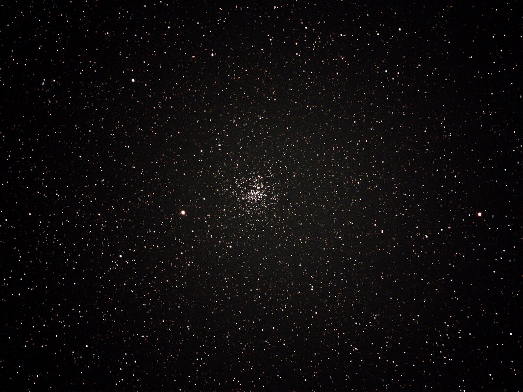
m37 Salt-and-pepper cluster
Settings: 0.75 second exposure, 135 gain, 45-255 histogram, 10 stacked images
Settings: 0.75 second exposure, 135 gain, 45-255 histogram, 10 stacked images
Second Night
I had my second night with the Hyperstar C6 + DS10c viewing session on Tuesday 2/6/2024. It was also a clear night in my backyard and about 50 degrees, with humidity of 55%. The SkyGlow and humidity gave me some grief again trying to view nebula. So, I decided to give the filter drawer a try and inserted a 2” SkyGlow filter hoping it would help, which it did. The first thing I realized though was the added glass of the filter in the optical train changed my focus. So, I slewed to a bright star, used the Bahtinov focus mask and brought it back into focus. Using a filter also increased the exposure time some, but at f/2 it was still fast and definitely helped with my Bortle 6 skyglow.
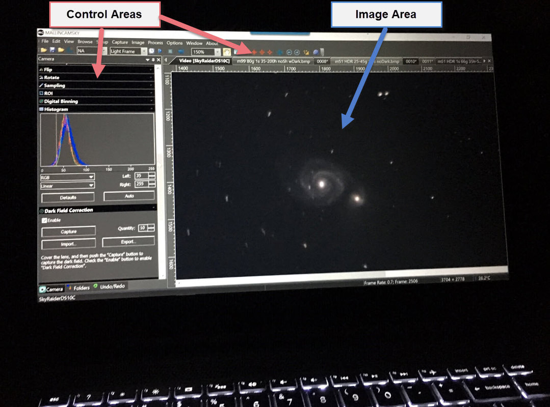
I was pleasantly surprised that the exposure time was still within the crowd-pleasing range for outreach. Looking at the list below, you can see that my exposure time was still under 2 seconds even with this filter in place with the DS10c at bin 1. I did begin to notice some vignetting with the Hyperstar on the C6, but to me it was OK for outreach where speed of seeing a nice image is needed. What really made this effective was the use of ROI which produced a significant difference in stacking speed since only the pixels of the region of interest were being transferred from the camera to the computer and stacked. Also the image cropping when using ROI reduced the visible vignetting.
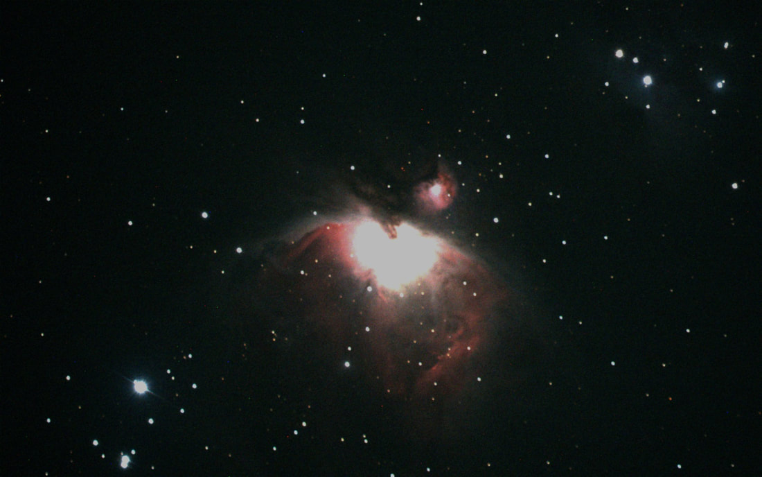
The Andromeda Galaxy image using ROI 2200x1700 enabled MallincamSky to stack 50 1.6-second images in 1.5 minutes. Even though the Crab Nebula was small, you do begin to see some detail in its ROI image. The Orion Nebula was also small in the full field of view image, but note that it was produced by a 0.6 second exposure with no stacking! I included two 1600x1000 ROI images of the Orion Nebula, each stacking 30 1-second images at a lower gain. I used LHDR in the last one to enable the core stars to be visible. Notice that I started it with same the exposure as the other one and then dropped the exposure briefly at the end using LHDR to populate the center core.
The SkyGlow filter was in place for all the following images.
I had my second night with the Hyperstar C6 + DS10c viewing session on Tuesday 2/6/2024. It was also a clear night in my backyard and about 50 degrees, with humidity of 55%. The SkyGlow and humidity gave me some grief again trying to view nebula. So, I decided to give the filter drawer a try and inserted a 2” SkyGlow filter hoping it would help, which it did. The first thing I realized though was the added glass of the filter in the optical train changed my focus. So, I slewed to a bright star, used the Bahtinov focus mask and brought it back into focus. Using a filter also increased the exposure time some, but at f/2 it was still fast and definitely helped with my Bortle 6 skyglow.
I was pleasantly surprised that the exposure time was still within the crowd-pleasing range for outreach. Looking at the list below, you can see that my exposure time was still under 2 seconds even with this filter in place with the DS10c at bin 1. I did begin to notice some vignetting with the Hyperstar on the C6, but to me it was OK for outreach where speed of seeing a nice image is needed. What really made this effective was the use of ROI which produced a significant difference in stacking speed since only the pixels of the region of interest were being transferred from the camera to the computer and stacked. Also the image cropping when using ROI reduced the visible vignetting.
The Andromeda Galaxy image using ROI 2200x1700 enabled MallincamSky to stack 50 1.6-second images in 1.5 minutes. Even though the Crab Nebula was small, you do begin to see some detail in its ROI image. The Orion Nebula was also small in the full field of view image, but note that it was produced by a 0.6 second exposure with no stacking! I included two 1600x1000 ROI images of the Orion Nebula, each stacking 30 1-second images at a lower gain. I used LHDR in the last one to enable the core stars to be visible. Notice that I started it with same the exposure as the other one and then dropped the exposure briefly at the end using LHDR to populate the center core.
The SkyGlow filter was in place for all the following images.
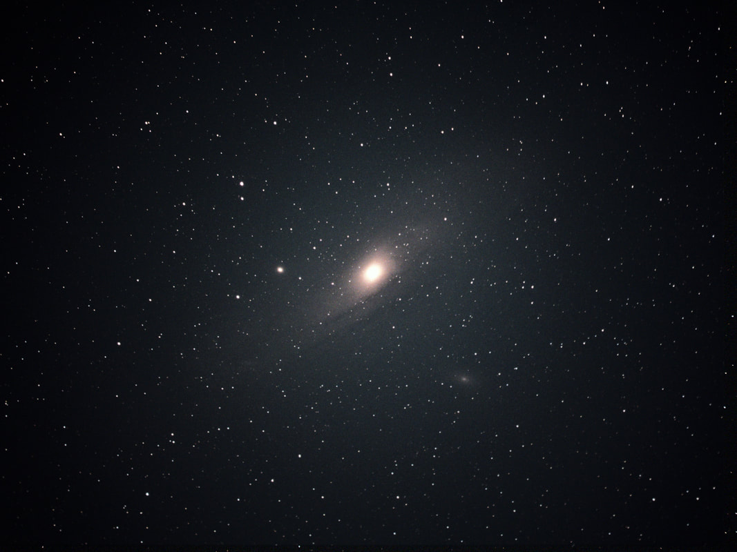
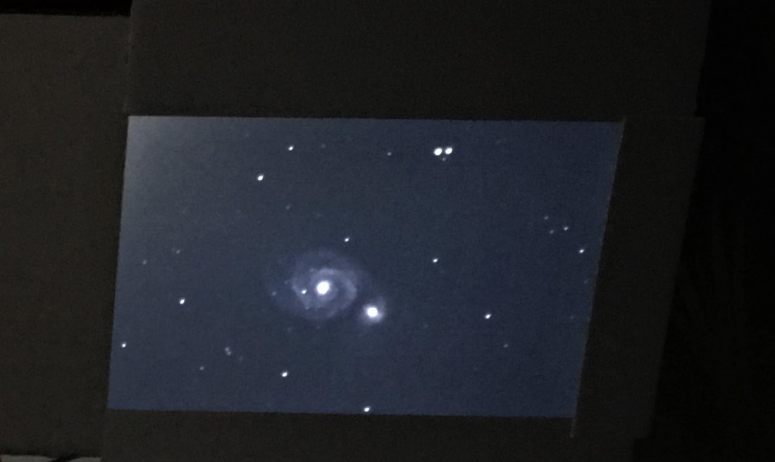
m31 Andromeda Galaxy
Settings: 0.75 sec then 1.2sec LHDR, 160 gain, 95-255 histogram, 20 stacked images
Settings: 0.75 sec then 1.2sec LHDR, 160 gain, 95-255 histogram, 20 stacked images
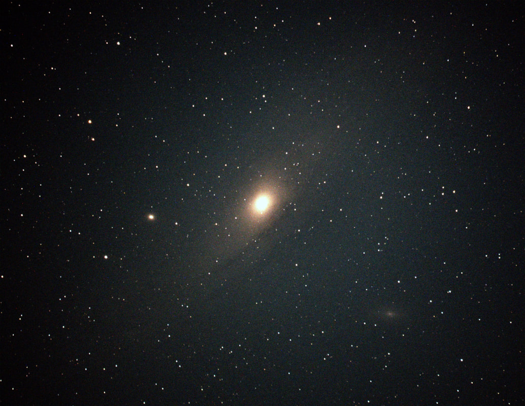
m31 Andromeda Galaxy
Settings: 1.6 sec, 160 gain, 130-255 histogram, 50 stacked images, ROI 2200x1700, total time 1.5 min
Settings: 1.6 sec, 160 gain, 130-255 histogram, 50 stacked images, ROI 2200x1700, total time 1.5 min
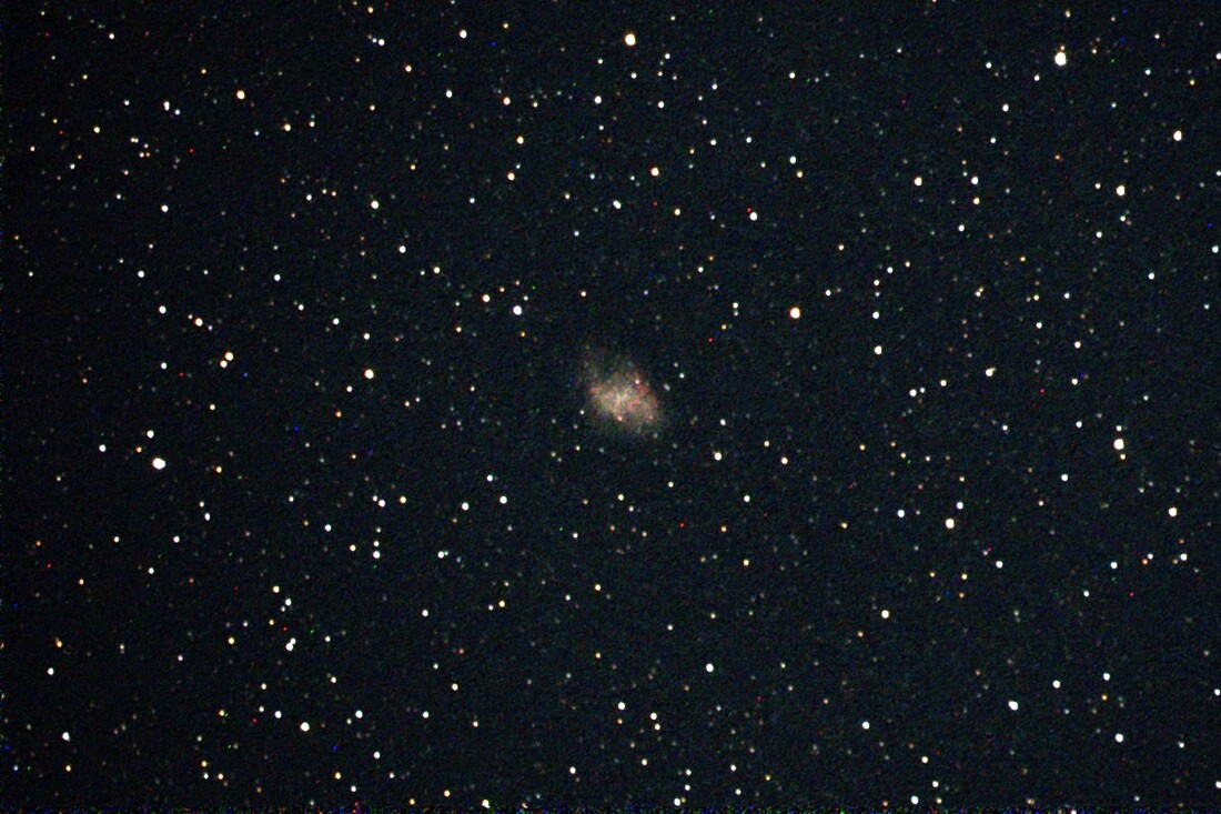
m1 Crab Nebula
Settings: 2 sec, 160 gain, 80-255 histogram, 55 stacked images, ROI 1200x800
Settings: 2 sec, 160 gain, 80-255 histogram, 55 stacked images, ROI 1200x800
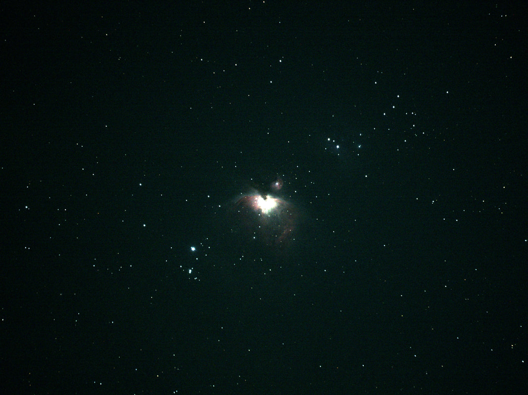
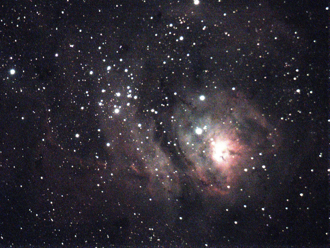
m42 Orion Nebula
Settings: 0.6 second, 160 gain, 20-255 histogram No stacking
Settings: 0.6 second, 160 gain, 20-255 histogram No stacking
m42 Orion Nebula
Settings: 1 sec, 110 gain, 60-255 histogram, 30 stacked images ROI 1600x1000
Settings: 1 sec, 110 gain, 60-255 histogram, 30 stacked images ROI 1600x1000
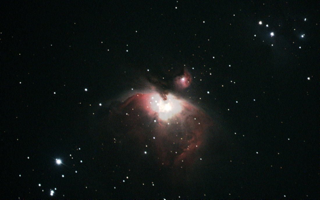
m42 Orion Nebula
Settings: 1 sec then briefly 0.2s LHDR, 110 gain, 60-255 histogram, 30 stacked images, ROI 1600x1000
I am pleased how the C6 with Hyperstar and DS10c work well together, and I believe it will be a good portable combination.
Note: If your Celestron 6” secondary mirror does not have a plate with a knob, for further instructions click: installing-secondary-mirror-mounting-plate-wknob-on-celestron-6.html


 RSS Feed